A complete cooker is a working system
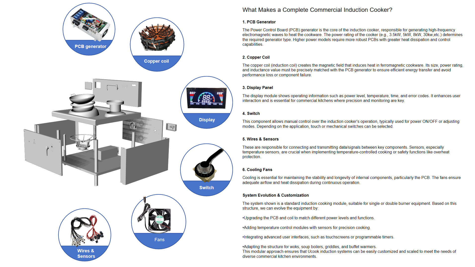
The image above illustrates the basic structural and functional components of a commercial induction cooker. The generator, induction coil, operator controls, display, sensors, wiring and cooling system each perform a different task, but none can be selected in isolation.
A dependable appliance comes from matching these elements to the cooking application, electrical supply, cookware or vessel, operating duty and cabinet structure. This configuration then forms the foundation from which different commercial models and functions can be developed.
- PCB generator and power stage
- Application-matched induction coil
- Display and operator controls
- Wiring harnesses and temperature sensors
- Cooling fans and defined airflow
- Mechanical structure and service access
PCB generator: power must match the application
The PCB generator converts the incoming electrical supply into the high-frequency power used by the induction coil. Its rating and architecture must suit the target voltage, phase, power level and continuous operating duty.
A higher kilowatt label alone does not create a better cooker. Generator capability, coil design, cookware load, cooling capacity and protection logic must operate inside the same validated range.
- Confirmed voltage, phase and frequency
- Required cooking power and duty cycle
- Compatible coil and load range
- Thermal management and protection
- Control and sensor interfaces
Induction coil: where power meets the cookware
The copper induction coil creates the magnetic field that transfers energy into ferromagnetic cookware or a compatible cooking vessel. Coil diameter, shape, winding, support and distance from the vessel all influence useful power transfer and temperature distribution.
Flat hobs, concave woks, stockpots, griddle plates and fryer tanks do not share one universal coil. The coil and generator must be developed and tested as a pair around the real load.
Controls, display, wiring and sensors
The display and switch are the operator-facing part of the cooker. They can show power, temperature, time, operating status and fault information, while the control method may use a mechanical switch, keys or a touchscreen according to the application.
Behind that interface, wiring and sensors connect the system and provide the information needed for control and protection. Sensor type, position, logic and cable routing must match the approved platform; a similar-looking component is not automatically interchangeable.
- Power and mode control
- Temperature and time display
- PCB, coil and vessel sensing where required
- Fault indication and protective response
- Controlled connectors and wiring interfaces
Cooling is part of the electrical design
Cooling fans do more than move air inside the cabinet. The design must bring suitable inlet air to the generator and coil area, prevent hot-air recirculation and leave enough space for inspection and replacement.
Fan capacity, inlet position, exhaust route, filters, partitions and ambient kitchen conditions all affect component temperature and service life. Cooling therefore has to be defined before the stainless-steel enclosure is finalized.
From 1 matched core to different products
Once the core system is matched and validated, it can become the technical foundation for a product family. The PCB and coil can be configured for different power levels; temperature-control modules and sensors can be added; and the operator interface can evolve from a switch to a display, touchscreen or programmed process.
The same platform logic can support countertop hobs, wok ranges, stockpot cookers, noodle cookers, fryers, griddles, boiling pans, tilting kettles and automated cooking equipment. Each derivative still requires review of its vessel, structure, airflow, controls and final test responsibility.
- Match the platform to one defined first appliance
- Build and validate a learning sample
- Lock the approved component and interface version
- Prepare assembly, QC and troubleshooting documents
- Plan recommended service parts before production
What InducParts delivers
InducParts supplies more than separate parts. We organize the generator, coil, controls, sensing, cooling and agreed wiring interfaces as one application-matched commercial induction platform, supported by installation guidance, technical training, QC checkpoints and spare-parts continuity.
The local manufacturer can focus on stainless-steel fabrication, final assembly, branding, market compliance, sales and field service. The objective is a product line that can be assembled, tested, maintained and repeated—not a one-time collection of components.
Common project questions
Can a commercial induction cooker be built by selecting a PCB, coil and fan separately?
Not reliably. The generator, coil, cookware or vessel, controls, sensing, cooling, wiring and enclosure must be reviewed and validated as one system.
Can one induction core be used for different commercial cooking appliances?
A validated core can become the basis of a product family, but each appliance still requires review of the load, coil relationship, operating duty, cooling, controls and final structure.
What does a complete InducParts SKD platform include?
The agreed scope can combine the matched generator, coil, controls, sensing, cooling and wiring interfaces with assembly guidance, QC checkpoints, technician support and a recommended spare-parts plan.
This article explains the system architecture, not a universal wiring or assembly instruction. Final specifications depend on the confirmed appliance, electrical supply, cookware or vessel, operating duty, enclosure and local manufacturing responsibility.