Start with the cooking process and vessel
Tilting kettles, bratt pans and mixing vessels may look similar from outside, yet they can serve different cooking, holding, frying, boiling or mixing workflows. The first project brief should therefore describe what the machine must do before naming a power module or parts list.
Share the vessel geometry, material, usable volume range, product behavior and operating sequence. These inputs establish the load that the induction system must work with and the conditions the complete appliance must be tested against.
- Cooking process and product behavior
- Vessel drawing and material
- Typical batch and operating sequence
- Cleaning, discharge and operator workflow
| Input to define | What the manufacturer should share | Platform decision informed |
|---|---|---|
| Cooking process | Product, batch pattern, vessel fill range and expected operating sequence | Vessel concept, heating duty and prototype test plan |
| Vessel and motion | Vessel drawing, material, tilt range, discharge direction and proposed actuator | Coil relationship, moving clearances and mechanical interface boundary |
| Mixing scope | Whether mixing is required, proposed tool and operator workflow | Drive, control, access and integration responsibilities |
| Electrical and controls | Confirmed voltage, phase, frequency, operator interface and required operating states | Generator arrangement, control architecture and validation scope |
| Cabinet and cooling | Equipment layout, air entry, exhaust, partitions and maintenance access | Thermal layout and serviceability review before fabrication |
| Factory responsibility | Local fabrication, assembly, inspection, final testing and after-sales capability | Parts-kit, document, spare-parts and change-control scope |
Treat tilting and mixing as system interfaces
A moving vessel changes the relationship between the cooking chamber, induction coil, sensing, wiring, structure and service space. The proposed tilt direction, travel, resting positions and actuator boundary should be fixed before the cabinet is released for fabrication.
If the appliance includes mixing, define the proposed tool, drive arrangement, lid or guard relationship and operator sequence as a separate subsystem. InducParts can coordinate the agreed heating and control interfaces, but the project must assign responsibility for the mechanical system and final machine validation.
- Tilt direction and proposed motion range
- Actuator and mechanical-support boundary
- Cable, sensor and service clearances
- Optional mixing-drive and tool interface
- Cleaning access in working and tilted positions
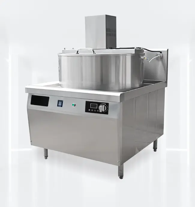
Match the induction core to the real moving vessel
A fixed stockpot platform should not be transferred to a tilting vessel without review. Vessel shape, base relationship, support structure and movement affect the coil geometry, generator matching, sensing layout and the clearances that must be maintained throughout operation.
The confirmed electrical supply and required cooking duty should be assessed together with the vessel. The final generator, coil and control configuration belongs in the approved project package and must be validated in the assembled machine.
Define control states and protective responses
The operator may need to manage heating, tilting and optional mixing through separate or coordinated controls. The project should list the intended operating states, permitted sequences and abnormal conditions without assuming that one generic control panel can serve every machine.
Working control and protective responses must be assigned to the agreed sensors and subsystems. Any motion-related permissions, alarms, shutdowns or restart behavior require confirmation and whole-machine validation by the responsible equipment manufacturer.
- Normal heating and holding states
- Tilt and optional mixing states
- Sensing and status indication
- Abnormal-condition response to validate
- Responsibility for the complete control sequence
Plan cooling, structure and service access together
The generator and coil still need a deliberate cool-air path inside a cabinet that also supports a heavy vessel and moving hardware. Air intake, exhaust, partitions and maintenance openings should be coordinated before the local factory completes the stainless-steel structure.
Service access should be checked with the vessel in its relevant positions. Components that need inspection or replacement must remain reachable without compromising the structural supports, motion system or hot-zone separation.
- Cool-air inlet separated from hot exhaust
- Space around generator, coil and moving structure
- Access with the vessel in working and tilted positions
- Protection from heat, moisture and cleaning activity
- Removal path for agreed service modules
Send an RFQ that fixes the delivery boundary
Manufacturers and engineering teams in India, Southeast Asia, Europe, the Middle East, Africa and Latin America should submit the actual target-market supply, machine concept and factory capability rather than rely on a regional assumption. This allows the project scope to distinguish the matched induction platform from locally fabricated vessel, structure and motion systems.
A useful RFQ includes the cooking process, vessel drawing, tilt and mixing concept, confirmed electrical supply, control expectations, prototype stages and after-sales owner. Detailed BOM quantities, coil data, wiring, design limits and customer identities remain controlled project information.
- Cooking process and vessel concept
- Tilt, discharge and optional mixing plan
- Confirmed voltage, phase and frequency
- Local fabrication and mechanical scope
- Prototype, pilot and final-test responsibility
- Service-part identification and change-control owner
Common project questions
Can a fixed-vessel induction parts kit be used unchanged in a tilting kettle?
Not safely by assumption. The vessel relationship, movement, structure, sensing, wiring clearances, cooling and complete control sequence require a project-specific review.
Are the tilt and mixing mechanisms included in every InducParts platform?
No. The heating, motion, mixing, controls and local-fabrication boundaries are agreed for each project according to the manufacturer’s capability and machine concept.
What should a manufacturer send for an initial tilting-vessel review?
Send the cooking process, vessel and cabinet concept, tilt and optional mixing plan, confirmed electrical supply, control expectations, factory scope and proposed validation stages.
This guide is a project-planning framework, not a vessel, motion, wiring or assembly specification. Final component selection and validation depend on the approved cooking process, vessel, movement, controls, electrical supply and manufacturing boundary.